When should a barndominium's plumbing be laid out?
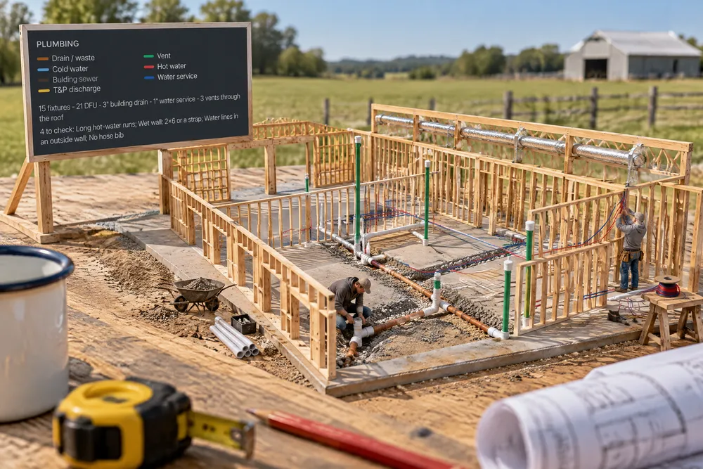
Before the slab is poured — the drains, the building drain's exit and the water service run under it. Our floor plan draws every drain sized from its fixture units at ¼″ per foot, the vents, cleanouts, supply and the utility trenches, and prints a P1 plumbing plan and P2 riser diagram to hand your plumber, who still routes it on site.
- Changing a line on a drawing before bidding costs little; moving a wall or window late in the build is expensive. BuildingAdvisor, Construction Change Orders ↗
The Layers menu gets Electrical, Plumbing and Mechanical. The drywall comes off and the studs show. Electrical: every circuit drawn in its own colour from the panel to its last box — up the panel wall, across the ceiling framing, down to the box, box to box through bored studs — switch legs and 3-way travellers, island boxes up through the slab, never up through a window or a door. The panel shows its working space (NEC 110.26); outside are the meter, the service and the ground rods; a legend lists each circuit with its breaker and wire, and the load calculation's service size. An independent check walks every wall and confirms no point is more than 6′ from a receptacle (NEC 210.52(A)) and that the required 20 A and dedicated circuits exist. Plumbing: every drain under the slab sized from the fixture units and laid at ¼″ per foot to the building drain and out to the sewer, vents up the walls and out through the roof, cleanouts, hot and cold PEX from a manifold beside the water heater, the T&P line, the water service below frost and the sewer trench. It flags what a plumber would mark up: trap arms too long, a 2″ vent up a 2x4 wall, hot runs over 50′. Mechanical: the air handler and condenser, supply trunks and a branch to every room, the return, bath fans and the range hood ducted out, and the dryer duct with its length check. The plan set gets P1 Plumbing plan, P2 DWV riser diagram and M2 Duct & gas layout, also in the trade-link packages. It is design intent to hand your electrician, plumber and HVAC contractor: they route it on site and size the equipment (airflow here is a stated rule of thumb until their Manual J). Built exclusively for post-frame and barndominium builders.
Also called: electrical layout 3d · circuit layout · panel schedule · receptacle spacing · plumbing layout · DWV riser diagram · under slab plumbing · vent stack · PEX manifold · HVAC duct layout · mechanical plan · plumbing plan sheet · barndominium plumbing · barndominium electrical
Every circuit, from the panel
The Electrical view takes the drywall off and draws each circuit in its own colour from the panel to its last box — across the ceiling framing, down to the box, box to box through bored studs — never up through a window or a door. The legend lists each circuit, its breaker and its wire, and the service size from the load calculation.
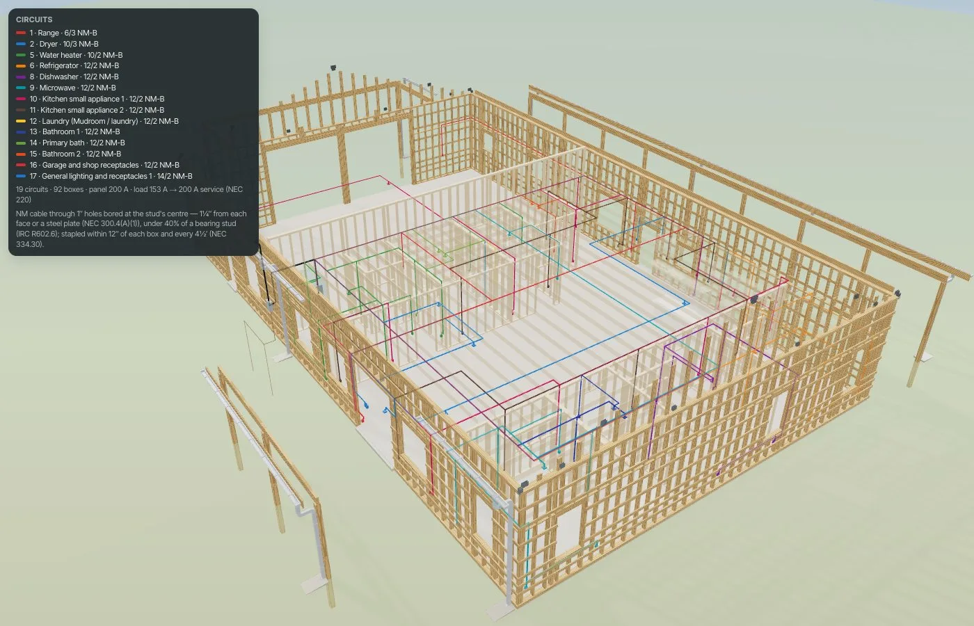
Outlets sat on the walls with nothing showing what fed them.
Every outlet is visibly on a circuit.
The panel and its working space
The panel shows its working space (NEC 110.26); outside are the meter, the service and the ground rods. An independent check walks every wall and confirms no point more than 6′ from a receptacle (NEC 210.52(A)).
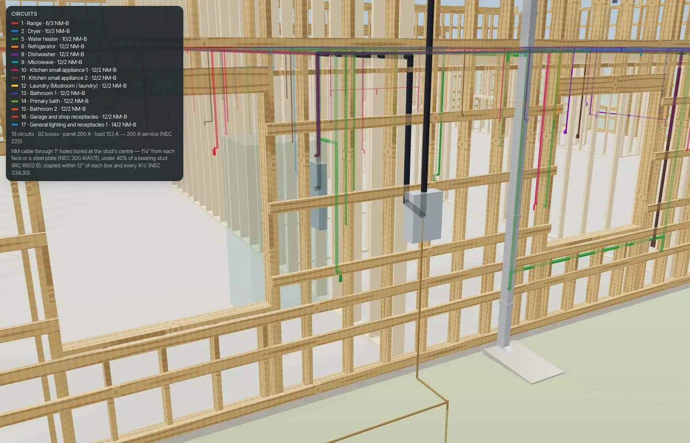
Receptacle spacing was eyeballed.
The spacing is checked, not assumed.
Drains, vents and water, sized
The Plumbing view draws every drain sized from its fixture units, the vents tied in the attic and out through the roof, cleanouts, and hot and cold PEX from a manifold to each fixture. The legend says what to check: long hot runs, a wet wall that needs 2x6 or a strap.
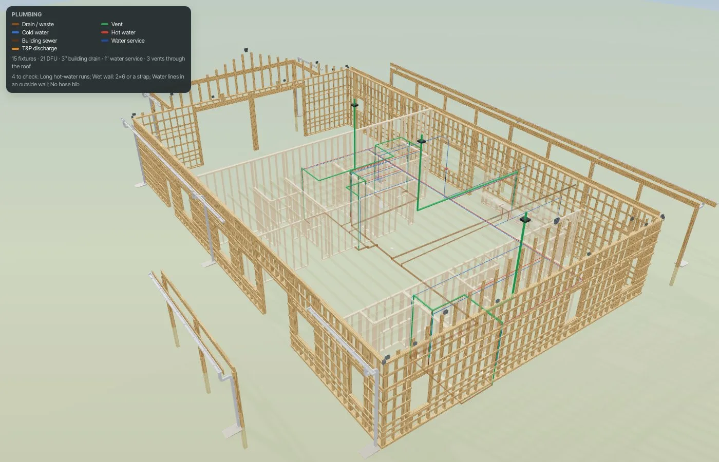
A 2″ vent up a 2x4 wall, found after the walls were up.
The plumber sees the job before the pour.
Under the slab
From below grade: drains falling at ¼″ per foot to the building drain and out to the sewer, risers into the walls, the water service below the frost line — the part that can't be changed after the concrete.
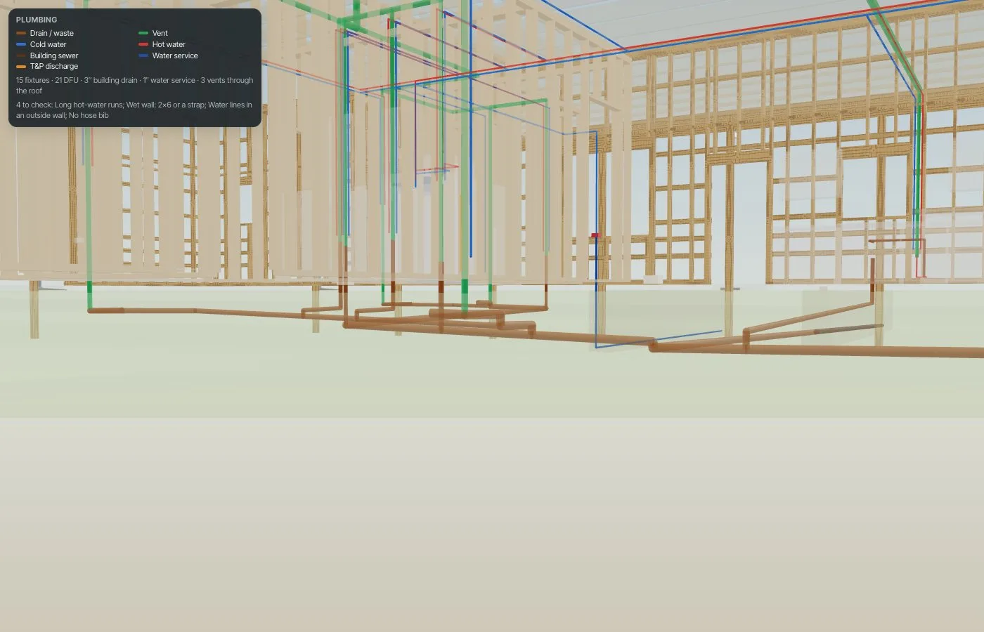
Plumbing rough-in located from memory before the pour.
Get the part under the concrete right.
Ducts in the attic
The Mechanical view draws the air handler, supply trunks and a branch to each room, the return over them, bath fans and the range hood ducted out, and the dryer duct with its length checked. Airflow is a stated rule of thumb — your HVAC contractor's Manual J sizes it.
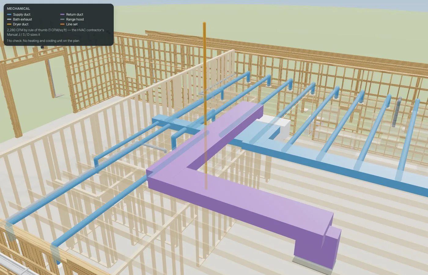
Duct runs discovered to have nowhere to go.
The ducts have a place before the trusses go up.
P1, the plumbing plan
The plan set gets P1 Plumbing plan: drains sized and tagged, cleanouts, vents, the drain exit with its depth, the water service and supply stubs.
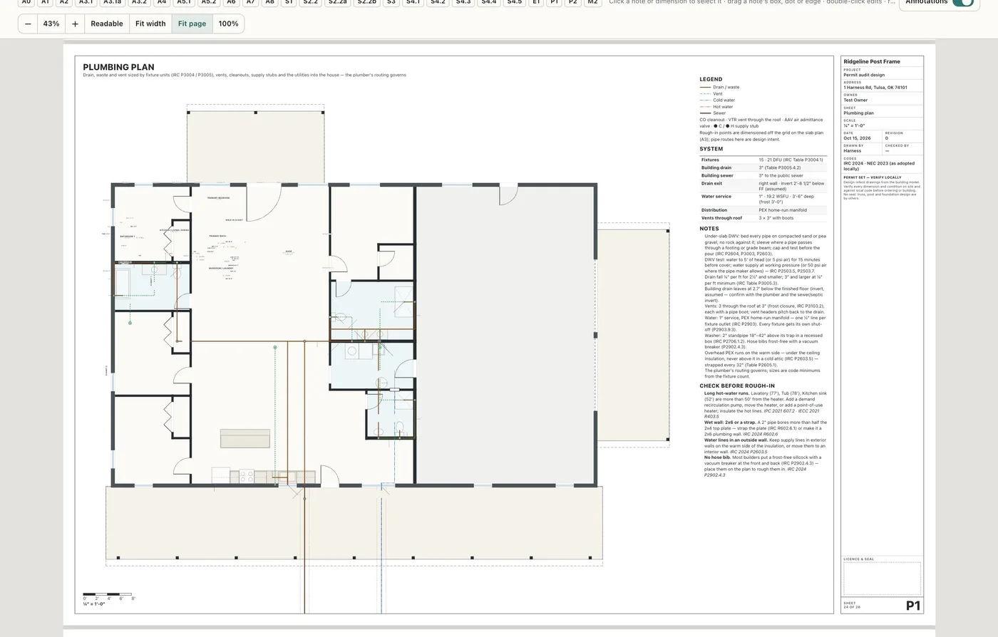
The plumber priced from a floor plan with no pipes on it.
A sheet the plumber can work from.
P2, the riser diagram
P2 DWV riser diagram with the fixture schedule and every water line — the drawing a plumber expects.
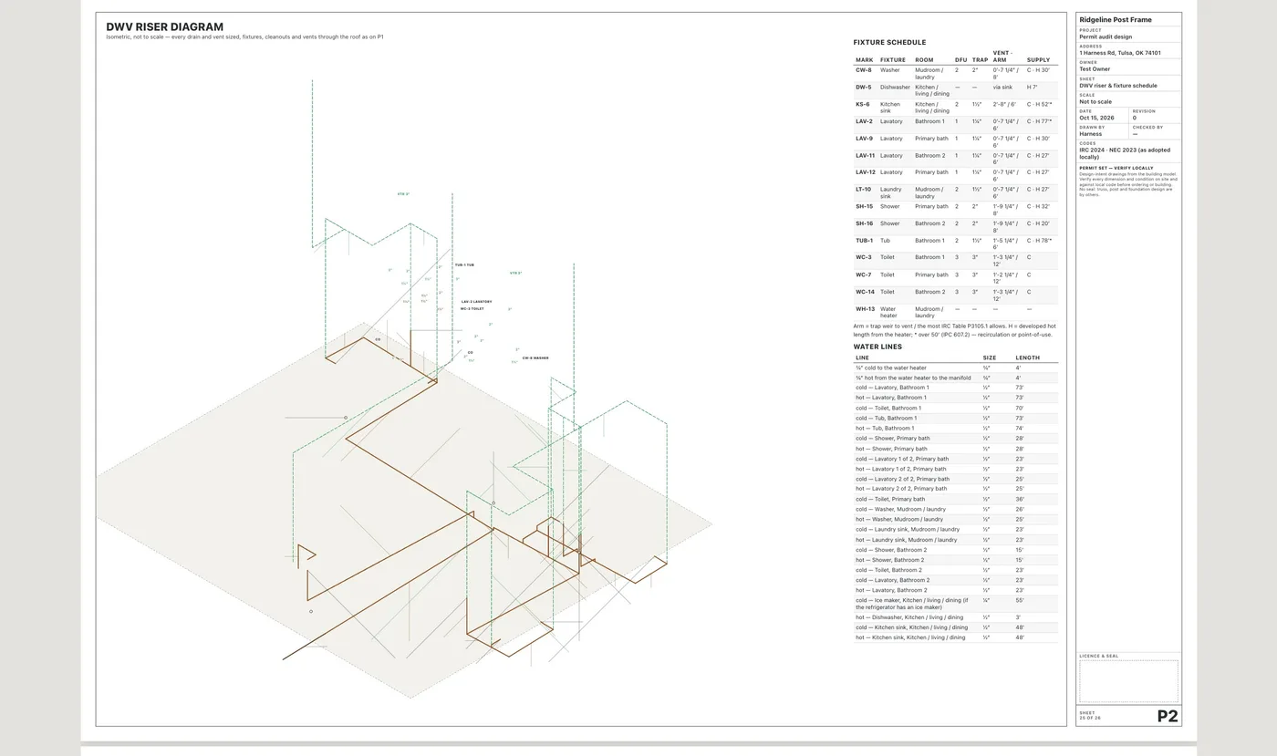
Riser diagrams drawn by hand, or not at all.
What the inspector asks for, already drawn.
M2, ducts and gas
M2 Duct & gas layout: trunks and branches with their sizes, the airflow per room (labelled a rule of thumb), exhaust and dryer ducts with their length check, and gas pipe sizes when the plan burns gas.
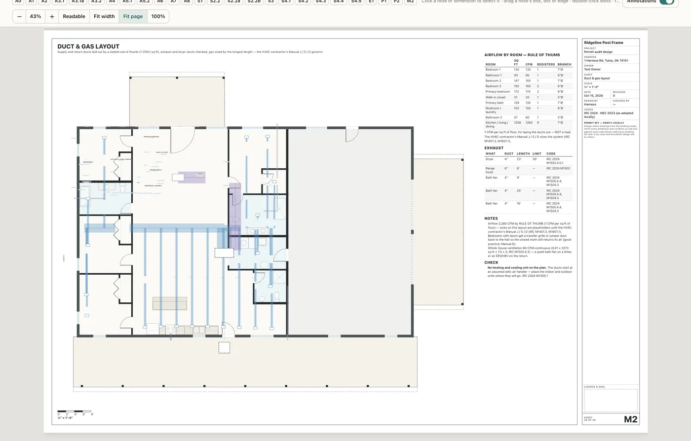
Mechanical left off the drawing set entirely.
The HVAC contractor starts from the house, not a blank page.
- 1Turn on Electrical, plumbing and mechanical views in Settings → Beta features.
- 2Draw the floor plan and place its electrical (Place code-minimum electrical does a room or the whole floor).
- 3In 3D open Layers and choose Electrical, Plumbing or Mechanical; read the legend for sizes and what to check.
- 4Open the Plan set for P1, P2 and M2 beside E1, or send them in a trade link.
Customers compare a turnkey barndo quote with kit prices that have no plumbing, electrical or interior at all. The trades are where the real house is — and where a layout nobody drew turns into a vent that won't fit a 2x4 wall, a bath 77 feet from the water heater, or outlets that were never on a circuit. Drawing the circuits, the pipes and the ducts from the floor plan, and flagging what a plumber or electrician would mark up, moves those discoveries from the rough-in to the drawing — where changing a line still costs almost nothing.
- Outlets on the plan with nothing showing how they're wired
- Plumbing nobody drew before the slab
- Vents that won't fit the wall they're in
- Long hot-water runs found after move-in